Founded in 1987, Liming Heavy Industry specializes in the production of stationary crushers in medium and large models, mobile crushing plants, and ball mills. With over 30 years of technical experience, the company adopts advanced production technologies from the United States, Germany, Australia, and other countries. The company's professionalism and product quality are comparable to well-known international brands in the industry.
Best Mobile Crusher Plant for Mining Projects in Africa
June 18th 2026
In our recent field tests across remote copper and aggregate sites in Sub-Saharan Africa, the biggest threat to profitability is not the rock hardness—it is the 30-day waiting period for concrete foundation curing. Operators bleed capital while steel sits idle in the dust. You cannot generate revenue from a machine that is waiting for civil engineering work to finish. The physics of heavy machinery demand stability, but modern pneumatic-chassis designs have rendered permanent concrete bases obsolete for initial site establishment.
Bypassing 30-Day Civil Engineering Delays
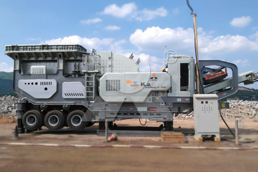
Pneumatic-mounted chassis design bypasses traditional concrete foundations, allowing immediate material processing upon site arrival.
Traditional stationary setups require massive excavations, rebar grids, and weeks of curing under the blistering sun. Look at the NK series layout. We utilize heavy-duty hydraulic legs that drive directly into the compacted earth. This mechanical architecture absorbs the kinetic shock of a 600mm granite block hitting a jaw plate without transferring fatal vibrations to the frame. Your capital payback velocity starts the moment the trucks unload the units, not a month later. The smell of diesel should mean crushed rock, not idling excavators digging foundation pits.
Waiting for infrastructure is a guaranteed way to inflate your initial investment. By switching to a tire-mounted system, operators slash their expenditure per shift immediately. The hydraulic cylinders allow for millimeter-precise leveling on uneven terrain, eliminating the need for perfectly graded ground.
Synchronized Equipment Matrix for 300tph Processing
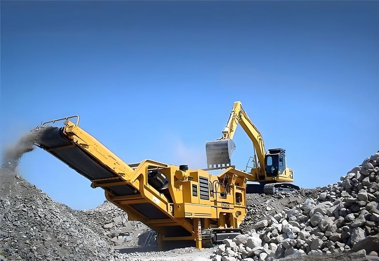
Executing a balanced flow rate across multiple mobile stages prevents choke-feeding and eliminates motor burnout.
To handle abrasive silica and massive feed sizes in off-grid locations, we have engineered the following circuit. This matrix guarantees that the primary jaw crusher perfectly feeds the secondary stages without triggering amperage spikes.
Process Stage
Recommended Model
Capacity (tons per hour)
Power (kilowatts)
Max Feed (millimeters)
Mounting Type
Primary Crushing
NK300J Jaw Plant
150-300
160
600
Pneumatic/Tire-mounted
Secondary Crushing
NK1213 Impact Plant
150-300
250
500
Pneumatic/Tire-mounted
Kilowatt Utilization in Off-Grid Environments
Direct-drive diesel-electric systems cut expenditure per shift by avoiding unpredictable regional grid fluctuations.
African mining operations frequently suffer from rolling blackouts. Relying on municipal power for a 250 kW rotor is a mathematical error. The NK series utilizes onboard diesel generators that synchronize perfectly with the high-capacity secondary impactor. When the blow bars hit a dense pocket of ore, the system dynamically adjusts the fuel injection to maintain the rotor’s rotational momentum. You feel the vibration change through your boots, but the throughput never drops.
Operating off-grid requires thermal management. The high-frequency metallic ping of aggregate hitting the screening deck indicates proper grading, but if your hydraulic oil overheats in 45°C ambient temperatures, the circuit shuts down. We integrate oversized cooling radiators directly into the K and NK series chassis. This prevents fluid degradation and keeps the hydraulic legs locked into their ground positions securely.
Field Wear Benchmarks: Synchronizing NK1213 with Hard Ore
Max Feed: 500 millimeters
Mounting Type: Pneumatic/Tire-mounted
Capacity: 150-300 tons per hour
Power: 250 kilowatts
Secondary Maintenance Interval: 400 hours
Technical Index: LH-BEST MOBILE CRUSHER PLANT FOR MINING PROJECTS IN AFRICA-April/2026-Ref-#91844
Site Lead’s Log: Addressing Pneumatic Setup Frictions
Why does the hydraulic leveling system lose pressure after 48 hours of crushing? Look at the thermal expansion rates. In 40°C heat, hydraulic fluid expands, and as it cools violently at night, micro-contractions cause pressure drops if the mechanical locking pins are not fully engaged after deployment. Can the NK1213 rotor handle un-blasted oversized boulders? A cheap rotor is just scrap metal waiting to happen. The 500 millimeter max feed limit is a hard physical boundary; pushing 600mm boulders past the curtains will shatter the blow bars and spike the 250 kilowatt motor instantly. How do we stop dust ingress from destroying the generator air filters? Do not ignore the wind direction. Position the primary jaw’s discharge conveyor perpendicular to the prevailing winds, or the 300 tons per hour of crushed fines will choke the intake manifolds within a single shift. What causes the entire chassis to bounce during heavy loading? Based on field telemetry, bouncing occurs when the hydraulic legs are deployed onto uncompacted topsoil. You must scrape the top 100 millimeters of loose dirt away before extending the leveling cylinders to hit stable earth.
Securing Production-to-Cost Ratios in Remote Operations
Forcing a 250 kilowatt motor to fight through damp, high-friction ore without a solid mechanical foundation guarantees catastrophic bearing failure, yet operators can completely neutralize this threat by leveraging the pneumatic chassis of the NK series to achieve perfect geometric alignment over raw earth. Execute the hydraulic deployment sequence precisely as mapped.
Stop Guessing on Off-Grid Kilowatt Loads
“Assess your site’s physical readiness before committing capital to stationary iron.” — From the Desk of your Field Technical Director